Warpage as an interfering factor
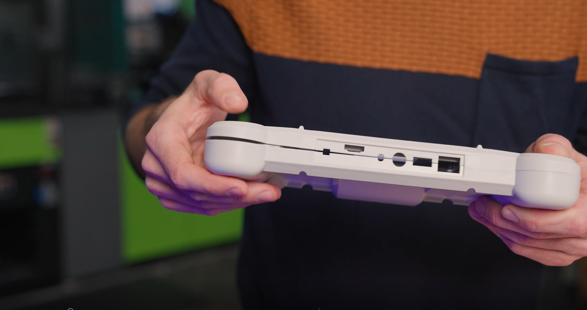
Whether injection molded or 3D printed, plastic parts often show unwanted deformation during the production. This warpage can than later be an issue when it comes to assembling the part. Until now, the only conventional way of determining warpage and its consequences was to use a physical fixture. This however has several disadvantages like:
- Measuring the part in the fixture becomes more difficult
- Fixtures are expensive and need maintenance
- Information from the unassembled state of the part gets lost
How to eliminate plastic warpage in Quality Control
Annoyed about plastic warpage and how it makes quality control of unassembled parts difficult? In this video, Toon shows you how to solve this problem: with the De-warp function that can be found in the full version of ZEISS INSPECT . It puts scanned plastic parts into a virtually assembled state, allowing you to check their dimensions as if they were assembled.
All functions shown are available in the current software version.
Got any questions on 3D scanning? Contact us via support@HandsOnMetrology.com
The solution: De-Warp in GOM Inspect Pro software
1
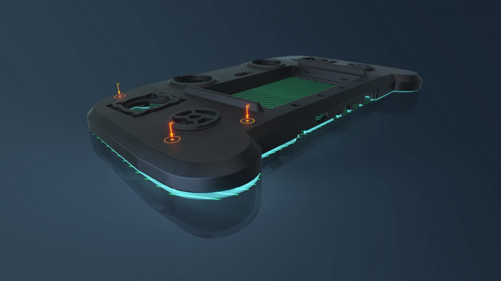
With the scan data, GOM Inspect Pro generates a mesh. The so called deformation model supports to mathematically model the deformation of inspected plastic parts. It is based on material properties and the CAD file to ensure detailed predictions of the parts behavior.
2
In order to know where virtual forces need to be applied, points for the assembly have to be pre-defined.
Finite Element Analysis in the GOM Inspect Pro software then helps to determine part deformation. The digital twin of the part gets adapted and inspection results are recalculated accordingly.
The user benefits from the illustration of assembled and unassembled state. The switch between the states allows for even more exact quality control.

