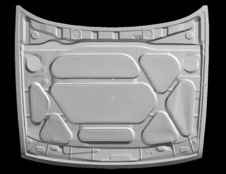
Big tools or dies for sheet metal work are mostly milled out from casted blanks. To produce these blanks, models are built using easy to process materials (Styropor or similar). Then foundry relevant additions, such as inlets and outlets are added. Then the form is imbedded in casting sand. After the backing of the form, the model material is burned out and the casting is made. The blank has to have excess material to compensate for deviations in the imbedding and the casting. In addition the blank has to have excessive material in the active areas to allow machining and hand tuning of the tool to produce the requested form and surface quality of the part in the stamping process (Fig. 1).
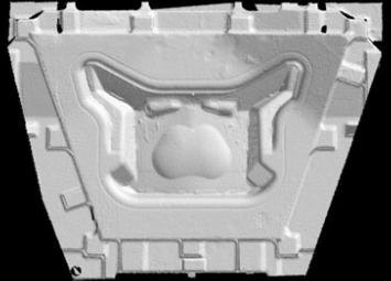
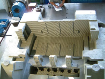
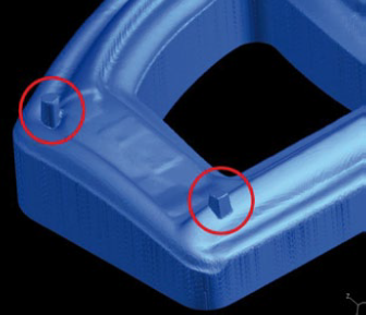
For the machining, the blank is aligned and bolted down on the worktable of an appropriate big horizontal milling machine. First usually the bottom is machined to a flat plane and then the blank is turned and the coarse contour of the tool is visible. As the processing time of the blank on the milling machine is a mayor cost, a time reduction is very welcome. Therefore big blanks are often inspected and alignment marks are manually applied on the blank before its positioning on the milling machine. Based on the marks, the blank is positioned on the milling table, aligned and bolted down. With the help of the pro line feature of the ATOS Q “back projection” these marks can be projected live onto the part. Then, usually casting specific modifications are removed by cutting them off or milling them down in manual control. Then the first contact point of the milling tool and the blank is defined letting the cutter work in the air with careful manual approach of the cutter to the blank. From this starting point the roughing is started. As the cutting depth is not uniform and can not be predicted by the CAM software, a slow feeding rate has to be used, with manual supervision
and correction.
Based on measurements with manual calipers a safe or optimized alignment of a big and complicated blank is not possible. A bad alignment can even ask for deposition welding to be able to machine all relevant surfaces of the future tool. For the digitizing of blanks ZEISS has added a large measuring area to the ATOS. For the digitizing of the big casted blanks, markers are applied on the blank. Then a central view is captured. Then additional views are captured and automatically transferred into the existing scanned data. Based on this technique, blanks with up to 5 x 3 meter size can be digitized in one hour keeping the requested accuracy. The export data from the ATOS system is either a file in “stl” format or section data. By the use of ZEISS reverse engineering software we can also create a CAD File. The ATOS export data can be directly imported in CAM systems such as TEBIS (“SCAN” module) or WorkNC (“NCSpeed” module from Sescoi Inc). Based on the actual data, the form of the blank can now be fitted into the needed tooling geometry. Then an optimal fit can be defined with minimized processing time.
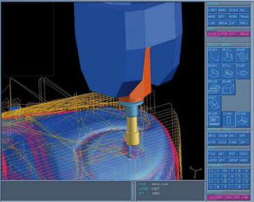
In addition an optimized and collision free cutting path can be calculated, with ideal cutting parameters and minimized cutting time to generate the tool from the blank in a predictable, fast, save and unmanned operation. Used is the above described process at BMW, Mercedes and Audi, in Germany, in collaboration with TEBIS and SESCOI. In the actual case, the time on the milling machine could be reduced from 48 hours to 8 hours. Important for the customer was, in addition to the time and money saving, the reliable, save and predictable process.
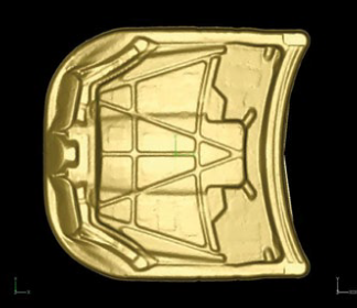
Automotive customers start to ask for ready to use tools, with a digital description of the actual tooling form from their suppliers. Based on this data, a quality control and traceability process can be started. Wear can be quantified, rework of the tool can be ordered and tested with a well defined master form and, if needed, an accurate copy of the tool can be produced fast. The scanner can also be used to scan the tool for this application. To get the needed high accuracy, ATOS is calibrated to digitize a smaller measuring area. Markers are attached to the tool and photogrammetry is used to define the accurate position of this markers. Then the sensor is utilized to scan the tool and insert the digitized data into the grid defined by the markers. Operating with the ATOS technology, an accuracy of the scanned data of few hundredths of a millimeter can be guaranteed.
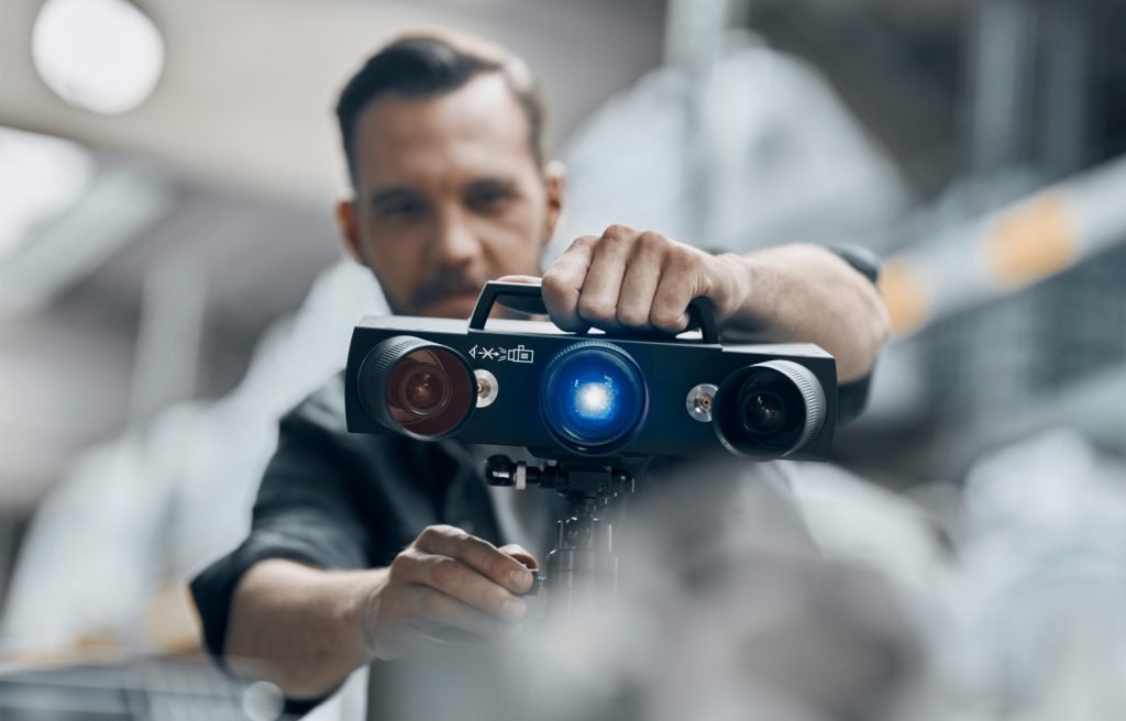
The ATOS sensor is the standard for the digitizing in design, in product development and in quality control. The two cameras used in the ATOS scanners verify the calibration of the scanner in each measurement and are therefore a necessity for the use of a transportable system in quality control applications. Also the change of the measuring area with calibration based on a certified artifact is done by the user in a few minutes. Using this potential, the ATOS can be adjusted to different customer needs and deliver accurate and efficient results.
