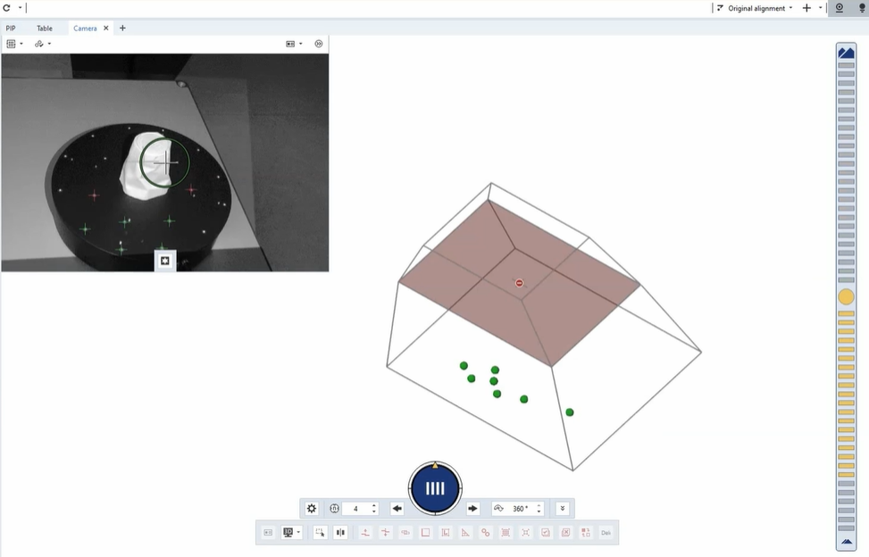
The measuring volume and the right distance go hand in hand when it comes to collecting all points necessary for your inspection task. The measurement volume is predefined by the lenses and determines the area in front of the scanner in which objects and thus accurate data are captured. The correct working distance comes into play here in order to position the object precisely in this measuring field.
Guidance for fast distance correction
To help you select the right distance, we developed some guidance for your next measuring task. These ensure the correct positioning of the 3D scanner and are integrated into the software and hardware solution of choice.
1. Distance radar
If you want to correct the distance in the software, you get to use the distance radar. A scale on the right hand side of the screen indicates whether the object is positioned correctly in order to collect all necessary points. If that is the case, the radar illuminates green and is in a neutral position. If you are too close to the object, the radar points upwards and becomes red. The radar becomes yellow, if you are too far away from the scanned object. You can thus easily correct the distance accordingly.
2. Laser indicator
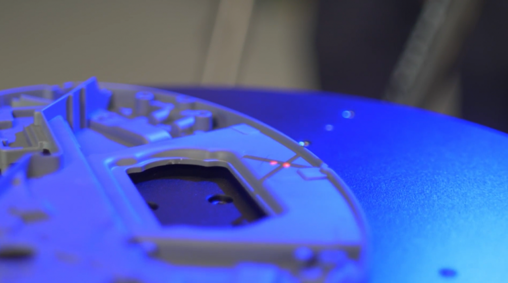
If you want to work more mobile or can’t control the screen on the laptop, the 3D scanners come with a laser indicator. It is projected onto the part while scanning and shows, whether you are distanced optimally for your application. T-SCAN hawk 2 is working with 2 red, intersecting laser lines to indicate the right distance. When working with GOM Scan 1 and ATOS Q, parallel laser points on a black cross symbolize, if your working distance is correct.


Get more in-depth information
Watch our latest How-to for more detailed explanations on how to choose the right distance to your object for 3D scanning.